OFDM
For real OFDM look at the DRM system, an open source receiver
available from sourceforge
and get technical specification TS 101 980 from the European Telecommunications Standards Institute.
This is an experiment in feeding 8 signal sources of varying pulse
widths to an inverse DFT to see the spectrum and get an idea of
the orthogonality of it. We create 8 vectors of size 32, and
vary the duty cycle from 3-on, 29-off (9%) to 24-on, 8-off (75%) in steps of 3,
and look at the resulting spectrum and how they interact. We are
also exploring ways of feeding a meangingful parallel signal to the iDFT.
This setup creates 8 vector sources, interleaves them, then feed that to
a serial-to-parallel which separates them out again for iDFT. That is
followed by a parallel-to-serial, a 250Khz mixer to shift the band up from
all negative frequencies, then the usual fft-sink, for display.
BTW, I laid out some cash for "OFDM for Wireless Communications Systems" (Ramjee Prasad) only to find an important chapter online in pdf form here
The code:
#!/usr/bin/env python
#

from gnuradio import gr
from gnuradio import eng_notation
from gnuradio.eng_option import eng_option
from gnuradio.wxgui import stdgui, fftsink
from optparse import OptionParser
import wx, random

class app_flow_graph (stdgui.gui_flow_graph):
    def __init__(self, frame, panel, vbox, argv):
        stdgui.gui_flow_graph.__init__ (self, frame, panel, vbox, argv)

        self.frame = frame
        self.panel = panel


        sample_rate = 500e3

        fft_size = 8

	# create 8 vectors of varying duty-cycle
	# using tvec to create temporary data, then append
	# that list to vecs where it can be easily accessed
	vecs = []
	for i in range(1,9):
	  tvec = []
	  for k in range(0,3*i):
	    tvec += [1]
	  for k in range(3*i+1,32):
	    tvec += [0]
	  vecs += [tvec]

	# some different signals to play with
        thin = []
        for i in range(0,3):
          thin += [1]
        for i in range(4,32):
          thin += [0]

        fat = []
        for i in range(0,28):
          fat += [1]
        for i in range(29,32):
          fat += [0]

        fast = []
        for i in range(0,4):
          fast += [1, 1, 1, 1, 0, 0, 0, 0]

        pwm = [1,1,1,1,1,1,1,1,0,0,0,0,0,0,0,0,1,1,1,1,0,0,0,0,1,1,0,0,1,0,1,0]

        randvec = []
        for i in range(0,32):
          if random.random() > .5:
            randvec += [1]
          else:
            randvec += [0]

        faster = []
        for i in range(0,8):
          faster += [1, 1, 0, 0]

        ultra_fast = []
        for i in range(0,16):
          ultra_fast += [1, 0]


	src1 = gr.vector_source_c(vecs[0],1)
	src2 = gr.vector_source_c(vecs[1],1)
	src3 = gr.vector_source_c(vecs[2],1)
	src4 = gr.vector_source_c(vecs[3],1)
	src5 = gr.vector_source_c(vecs[4],1)
	src6 = gr.vector_source_c(vecs[5],1)
	src7 = gr.vector_source_c(vecs[6],1)
	src8 = gr.vector_source_c(vecs[7],1)

	inter = gr.interleave(gr.sizeof_gr_complex)
	self.connect ( src1, (inter, 0))
	self.connect ( src2, (inter, 1))
	self.connect ( src3, (inter, 2))
	self.connect ( src4, (inter, 3))
	self.connect ( src5, (inter, 4))
	self.connect ( src6, (inter, 5))
	self.connect ( src7, (inter, 6))
	self.connect ( src8, (inter, 7))

        s2p = gr.serial_to_parallel (gr.sizeof_gr_complex, fft_size)
        ifft1 = gr.fft_vcc (fft_size,False,False) # inverse, no windowing

        p2s = gr.parallel_to_serial (gr.sizeof_gr_complex, fft_size)

	rf_src = gr.sig_source_c (sample_rate,gr.GR_SIN_WAVE,250e3,1,0)
	rf_mix = gr.multiply_cc()

        self.connect ( inter, s2p )
        self.connect ( s2p, ifft1 )
        self.connect ( ifft1, p2s )
	self.connect ( p2s, (rf_mix, 0))
	self.connect ( rf_src, (rf_mix, 1))

        block, fft_win = fftsink.make_fft_sink_c (self, panel, "", 256, sample_rate)
        self.connect (rf_mix, block)
        vbox.Add (fft_win, 1, wx.EXPAND)


def main ():
    app = stdgui.stdapp (app_flow_graph, "USRP FFT")
    app.MainLoop ()

if __name__ == '__main__':
    main ()
which produces this output:

The thin, low duty-cycle signal is the fat, wide spectrum on the left,
while the high duty-cycle signal is the narrower peaks on the right -
that is, a constant on signal is a narrow peak, while a more highly
modulated signal is wider. If we change all signals to short pulses
we get this:
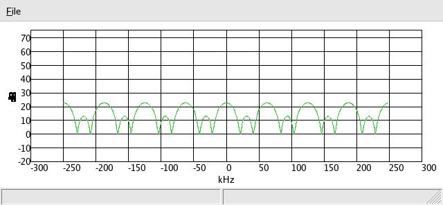
then just for grins put a wide signal in there somewhere:
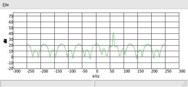
where we can see sig source #6 has changed to a peaked spectrum. Finally, putting
signal 'fast' in the source 3 slot we get this:

were we see they are still largely non-interfering with each other. Next add
pulse-width-modulation to slot 4:

then a random noise vector in slot 8:
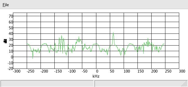
then a medium fast signal [1,1,0,0,1,1,0,0,...] in slot 7:
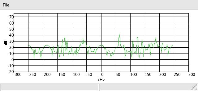
note the two peaks on each side of the cntral peak in slot 7. Finally
the fastest possible signal in 7:
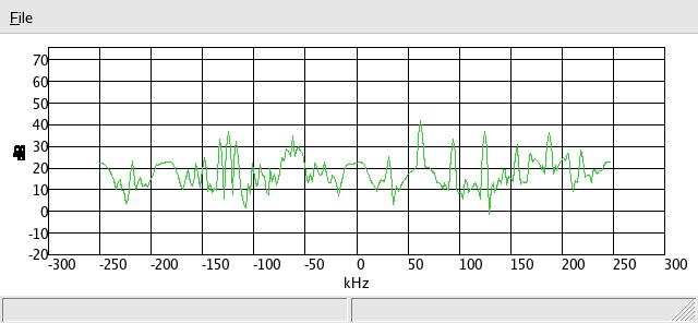
note the peaks are further apart. What if we put two ultra-fast signals
in adjacent slots? Trying 7 & 8:
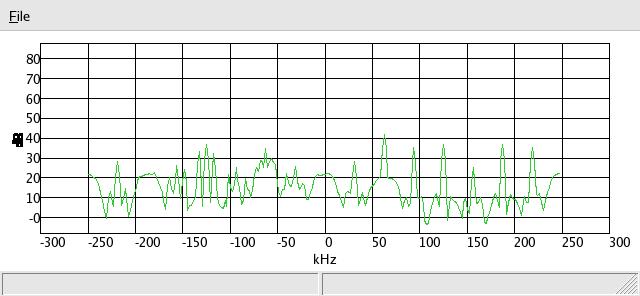
appearently they are interfering with each other at that rate, as the side
peaks are overlapping on the common channel boundary just above 150Khz.


