Experiment #4: series LC circuit
This verification experiment uses the 1nF capacitor and the 1.5uH
inductor connected in series
to the VNA on a breadboard and the 6" piece of RG-174.
I use the same calibration data files from experiment #1.
Then I run f_sweep_tr.py stopping at 10Mhz since they are known
to be "interesting" around 4MHz.
This creates a data file LC_series_refl_raw. This is compensated with
$ ./refl_calc_1.py calib_refl_open calib_refl_short calib_refl_load LC_series_refl_raw LC_series_refl_comp
and then display the results with the updated version of display_smith_data2.py
The displays:
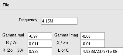
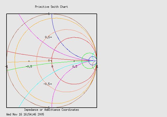
A series resonant LC circuit appears as a low impedance where inductive reactance
equals capacitive reactance. Above we can see the Smith chart point toward
the shorted, zero point, and the two components look like a .05uF cap and 1/2 ohm
resistor. If I bump the Powermate knob one tick into the inductive region, it changes
from a large capacitance of 50nF to a small inductance of 54nH. In theory a 1.5uH and 1nF series would also resonate at 4.109MHz.
f = 1 / ( 2 * π * sqrt( L * C ))