Experiment #2: 1nF capacitor in a breadboard
This verification experiment uses a marked 1nF capacitor connected
to the VNA with a breadboard and a 6" piece of RG-174.
I use the calibration data files from experiment #1:
calib_refl_open, calib_refl_short and calib_refl_load, since the
test jig is the same. Then I connect the 1nF capacitor and run f_sweep_tr.py,
creating a data file 1nF_refl_raw. This is compensated with
$ ./refl_calc_1.py calib_refl_open calib_refl_short calib_refl_load 1nF_refl 1nF_refl_comp
and then display the results with the updated version of display_smith_data2.py
The displays:
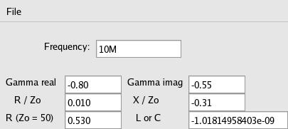
Again I'm pleased to see the displayed value of C remains between values like
-9.807e-10 (981pf) at low freq to -1.121e-09 (1121pf) at 20MHz. Above 20Mhz the value
ranges up to 1.254nF at 24.85MHz since the reactance is getting down to
10% of the system impedance and effecting accuracy I guess. The negative sign
for reactance indicates capacitive.