Experiment #1: 1.5uH inductor in a breadboard
This verification experiment uses a known 1.5uH inductor connected
to the VNA with a breadboard and a 6" piece of RG-174. With the
6" coax connected to the breadboard I run f_sweep_tr.py in reflection
mode (option -tr) from 250kHz to 25MHz with the coax OPEN, with a
SHORT, and with a 51 Ohm resistor load. This creates data files
calib_refl_open, calib_refl_short and calib_refl_load in a seperate
directory. Then I connect the 1.5uH inductor and run f_sweep_tr.py
again, creating a data file 1.5uH_refl_raw. This is compensated with
$ ./refl_calc_1.py calib_refl_open calib_refl_short calib_refl_load 1.5uH_refl 1.5uH_refl_comp
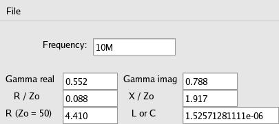
and then display the results with an updated version of display_smith_data2.py
which uses the reflection coefficients (Gamma) to compute and show the normalized
R and jX and the actual resistance and value of inductance or capacitance
in a 50 Ohm system (Zo = 50).
The displays:

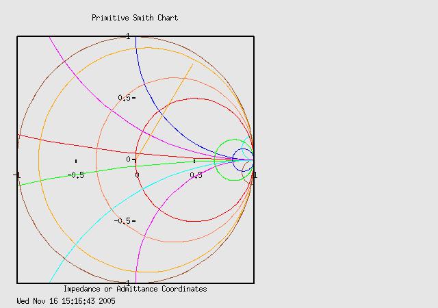
where I'm pleased to see the displayed value of L remains between values like
1.396e-06 and 1.4326e-06 over the entire frequency sweep of 250kHz to 25Mhz.
Exp. 1a - This time I put a 50ft length of RG-58 coax inbetween the
directional coupler and the breadboard. Then the system including the 50ft
cable is calibrated (open, short, load) and when the same 1.5uH inductor
is connected to the end of the coax, swept and plotted I get this similar
result:
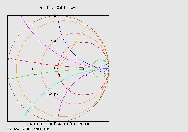
Note: The inductor is NOT a calibration standard, it is just a Jameco "1.5uH"
inductor. Measured with an AADE LC meter for
comparison, I get 1.56uH, an error of about 150nH in the first part and only
35nH in the long coax 2nd part.