Reflection Vector Analyzer (single frequency)
This page shows progress toward a VNA ala the TAPR model, using GNURadio
software, a USRP and a handful of Minicircuits parts. While the TAPR
device works to 100Mhz or so, this projected is limited to 25Mhz.
So far it will measure reflection coeffecients, or Gamma, of both magnitude
and phase relative to an incident signal, once calibrated at a single frequency.
EVENTUALLY I plan to include calibration across a frequency range in
both reflection and transmission. (See McDermott pp.7-9 for a good
explaination of calibration and compensation details).
Once reflection magnitude and phase are measured, it is straightforward
to calculate the normalized resistance and reactance (Rn and Xn here), then
the actual resistance and reactance (R and X), and since the frequency is known
the actual inductance or capacitance (L or C).
The software: smith_chart_4.py which needs
to find usrp_siggen.py and also uses Python module Gnuplot.py to create
the display.
The hardware schematic diagram:
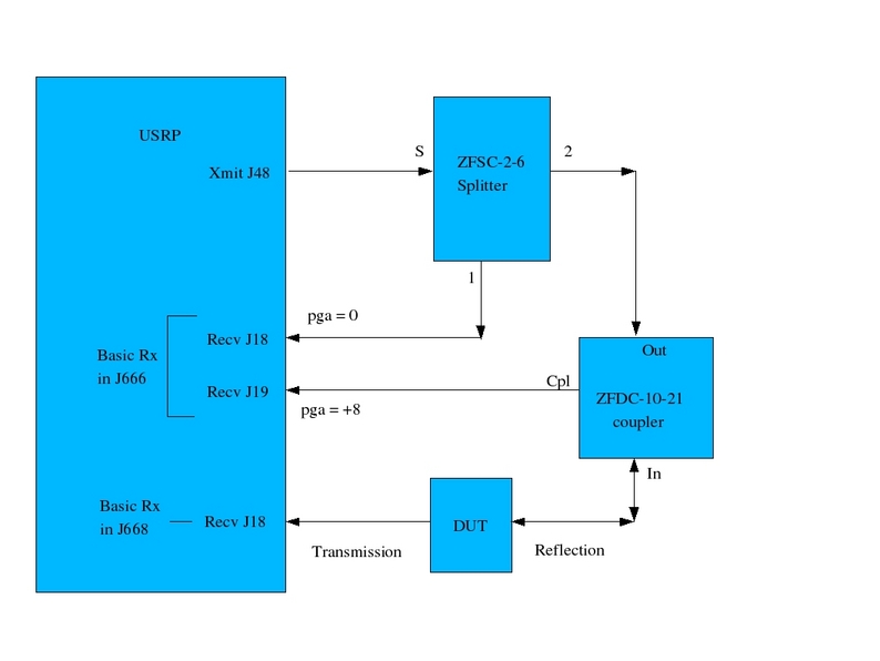
The +8db settting for the J18 pga is to compensate for the -10db loss in
return signal from the directional coupler.
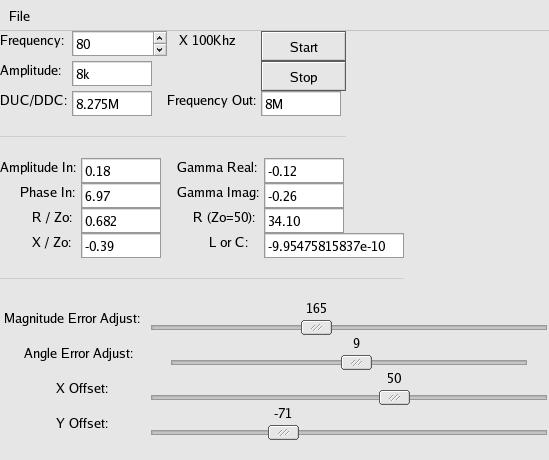
The control panel:
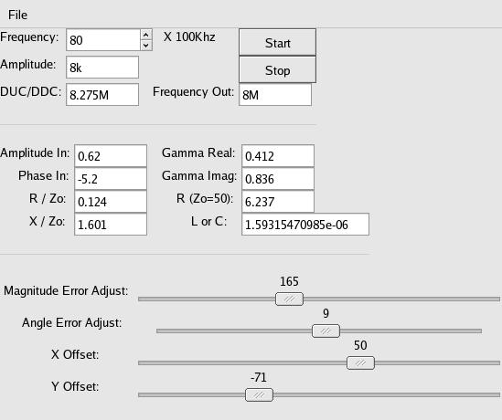
The above is shown running at 8Mhz with a 1.5uH inductor for a DUT.
Notice the box labled "L or C" displaying 1.59E-6.
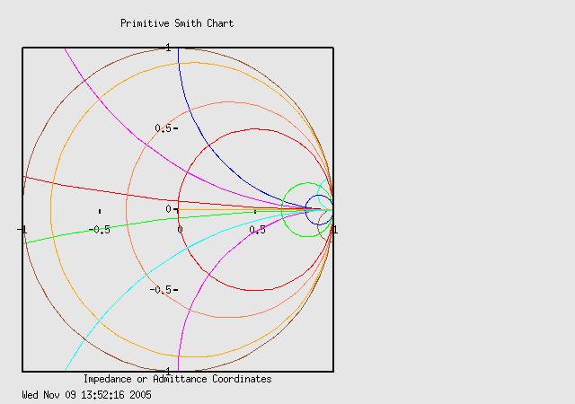
Next, a smith chart with the set running, calibrated and an 'open':
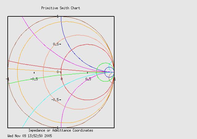
This next is with a 'short':
Lastly, this is the smith chart output of the system running 8Mhz, calibrated,
and a 33 ohm resistor in series with a 1000pf cap:

and the control panel showing 34.10 in the R(Zo=50) box and -9.95E-10 or
995 picofarads in the L or C box (negative reactances are capacitive, in
the lower half of the Smith chart and positive reactances are inductive and
in the upper half.)
All I do is calibrate for 'open' and 'short' and can get reasonable measurements
of L R and C if their reactances are somewhere in the Zo (50 Ohm) range. For instance, a
47 Ohm resistor reads 49.3 Ohms, with L or C reading 1.2E-8 or 12pF, which is
over 1600 Ohms reactance at 8Mhz. A 51 Ohm resistor reads 53.2, etc. Plug
in a 47pF cap and it reads -4.7E-11, etc.
If the frequency is changed it needs recalibrating. Consider this: at only 11Mhz, and with a .66 velocity factor, each inch of coax rotates the Smith chart
by one degree, and changing the frequency changes it's electrical length.